Controlled Attitude
1. Overview
1. Functions
- The
ControlledAttitudeclass provides a perfectly controlled attitude instead of free motion attitude dynamics by numerical propagation. - Users can set the attitude as sun pointing, earth pointing, and others for any direction in the spacecraft body frame. Of course, users can select an inertial stabilized attitude.
- It is useful for power, communication, and orbit analyses with S2E.
2. Related files
src/dynamics/attitude/attitude.hpp, .cpp- Definition of
Attitudebase class
- Definition of
src/dynamics/attitude/controlled_attitude.hpp, .cppControlledAttitudeclass is defined here.
src/dynamics/attitude/initialize_attitude.hpp, .cpp- Make an instance of
Attitudeclass.
- Make an instance of
sample_satellite.ini: Initialization file
3. How to use
- Inside the codes
ControlledAttitudeclass inherits theAttitudeclass, so other functions can access theControlledAttitudeclass by using get functions in theAttitudeclass.
- User I/F
- Firstly, users should set
propagate_mode = CONTROLLEDat the[ATTITUDE]section in thesample_satellite.inifile. - Users can set a target attitude in the initialize file. There are the following setting parameters:
main_mode,sub_mode,initial_quaternion_i2t,pointing_t_b, andpointing_sub_t_b. - Firstly, users select the control mode by using
main_modeandsub_mode. For the control mode. - When
main_modeis set asINERTIAL_STABILIZE,sub_modeis ignored, and the spacecraft attitude is fixed to theinitial_quaternion_i2tvalue in the simulation. - When
main_modeis set asHOGE_POINTINGmodes, the direction of the body-fixed frame defined bypointing_t_bis controlled to point the specific direction of the modes.- Ex. 1, the body-fixed +X axis directs to the sun when
main_mode = SUN_POINTINGandpointing_t_b = [1.0,0.0,0.0]. - Ex. 2, the body-fixed -Z axis directs to the earth center when
main_mode = EARTH_CENTER_POINTINGandpointing_t_b = [0.0,0.0,-1.0].
- Ex. 1, the body-fixed +X axis directs to the sun when
sub_modeis only used when users selectPOINTINGmodes formain_mode.sub_modeis defined to stop rotation around the pointing direction ofmain_mode. The selected sub-direction in the body-fixed frame cannot perfectly direct the target direction since the primary target and sub-target usually do not satisfy the vertical relationship.sub_modecannot beINERTIAL_STABILIZEand the same mode withmain_mode.- The angle between
pointing_t_bandpointing_sub_t_bshould be larger than 30 degrees. (90 degrees is recommended)
- Firstly, users should set
- List of attitude control mode
- INERTIAL_STABILIZE = 0
- SUN_POINTING = 1
- EARTH_CENTER_POINTING = 2
- VELOCITY_DIRECTION_POINTING = 3
- ORBIT_NORMAL_POINTING = 4
- orbit normal $n$ is defined as $n=r\times v$, where $r$ is radial direction and $v$ is velocity direction.
2. Explanation of Algorithm
1. Initialize function
1. overview
- This function initializes the target attitude and confirms that the setting parameters are correct.
- The parameter checklist
- Out of range check for both mode definitions.
main_modeandsub_modeis not the same- The angle between
pointing_t_bandpointing_sub_t_bshould be larger than 30 degrees.
2. inputs and outputs
- NA
3. algorithm
- NA
4. note
- NA
2. Propagate function
1. overview
- This is the main function executed in every loop of attitude dynamics calculation.
2. inputs and outputs
- inputs
- setting parameters
- outputs
- quaternion_i2b
3. algorithm
- Detail algorithm is described in the next function.
4. note
- NA
3. CalcTargetDirection
1. overview
- This function calculates the target direction according to the pointing mode.
2. inputs and outputs
- inputs
- control mode
- orbit class
- celestial information class
- outputs
- the direction of the target object
3. algorithm
- As written in the code.
4. note
- NA
3. PointingCtrl
1. overview
- This function calculates the
quaternion_i2b.
2. inputs and outputs
- inputs
- the main direction of the target object in ECI frame $t_m^i$
- the sub direction of the target object in ECI frame $t_s^i$
- the main controlled direction in the body frame $d_m^b$
- the sub controlled direction in the body frame $d_s^b$
- outputs
- quaternion_i2b
3. algorithm
- Firstly, the $DCM_{t2i}$, which is the frame transformation from the target frame to the inertial frame, is calculated using $t_m^i$ and $t_s^i$ with
CalcDCM. - Next, the $DCM_{t2b}$, which is the frame transformation from the target frame to the body-fixed frame, is calculated using $d_m^b$ and $d_s^b$ with
CalcDCM. - Finally, both DCMs are combined as follows. And
quaternion_i2bis calculated from the $DCM_{i2b}$. \[ DCM_{i2b} = DCM_{t2b} \cdot DCM_{t2i}' \]
4. note
- NA
3. CalcDCM
1. overview
- This function calculates a DCM from two given directions.
- The DCM represents the coordinate transform matrix from the new frame defined by the two directions to the original frame.
2. inputs and outputs
- inputs
- the main direction in the frame $a$ : $d_m^a$
- the sub direction in the frame $a$ : $d_s^a$
- outputs
- Coordinate transform matrix from the new frame to the original frame $a$
3. algorithm
- The first basis vector of the new frame is defined as the main direction. \[ e_1=d_m^a \]
- The second basis vector needs to be direct to the sub direction, but it should be vertical with $e_1$. \[ e_2 = \frac{(e_1\times d_s^a) \times e_1}{|(e_1\times d_s^a) \times e_1|} \]
- The third basis vector is defined as right-hand coordinate. \[ e_3=\frac{e_1\times e_2}{|e_1\times e_2|} \]
4. note
- NA
3. note
- Currently, the
ControlledAttitudeclass does not calculate angular velocity, and it is set as 0. The feature will be implemented in the near future.
3. Results of verifications
1. Inertial stabilize
1. overview
- To verify the correctness of pointing control
2. conditions for the verification
- input files
- default files
- initial values
- main_mode = sub_mode = INERTIAL_STABILIZE
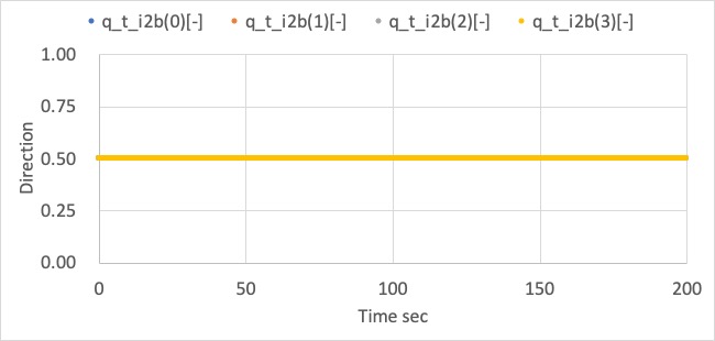
- initial_quaternion_i2b = [0.5,0.5,0.5,0.5]
3. results
- The inertial stabilize control is succeeded.
1. Pointing Control
1. overview
- Several cases described at the bottom were checked to verify the correctness of pointing control.
2. conditions for the verification
-
input files
- default files
-
cases
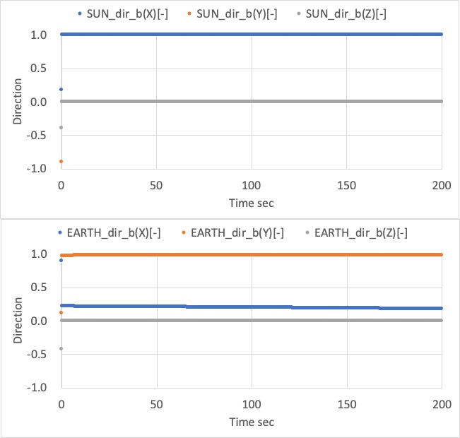
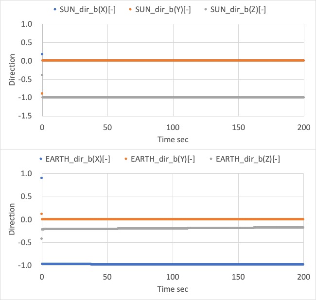
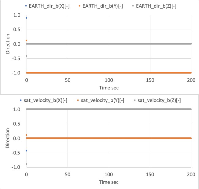
case main mode sub mode main_pointing_direction_b sub_pointing_direction_b 1 Sun Earth Center [1,0,0] [0,1,0] 2 Sun Earth Center [0,0,-1] [-1,0,0] 3 Earth Center Velocity [0,-1,0] [0,0,1] 4 Velocity Sun [0.707,0.707,0] [0,0,1]
3. results
- Case 1
- The spacecraft +X axis correctly directs to the sun, and its +Y axis roughly directs to the earth.
- Case 2
- The spacecraft -Z axis correctly directs to the sun, and its -X axis roughly directs to the earth.
- Case 3
- The spacecraft -Y axis correctly directs to the earth, and its +Z axis roughly directs to the velocity direction.
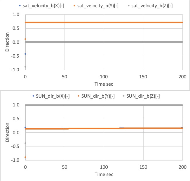
- Case 4
- The spacecraft +XY direction correctly directs to the velocity direction, and its +Z axis roughly directs to the sun.
4. References
- NA